The Prisma Business Centre in Levata di Curtatone
 The new headquarters are characterised by the unique triangular design of its base, incorporating VRF heat recovery systems to provide the best solution for primary climate control, with minimal use of energy.
A perfectly shaped triangular layout characterises the new Prisma Business Centre, which is located in Levata di Curtatone, on the outskirts of Mantua. The building is highly dynamic, and looks particularly striking when viewed along the line of with the apex. It is from this view that the all-glass building seems to stretch out like a sharp wedge above its base, and appears to almost lift itself above the ground beneath it.
The works reveal architectural and environmental challenges which are not to be underestimated: the choice of the shape - an isosceles triangle –, whilst offering the most spectacular visual effect with its geometric shape, did present some problems in terms of indoor space. The effort made to lighten the effect provided by the unique triangular design of the perimetral sections enhances the aerodynamics even further.
The strong and unmistakable design of the building, raised from the ground and aerial in vocation, is the creation of the Architect Salvatore Pellitteri.
The interior of the building reveals a surprising amount of space offered by the vast semicircular area on the ground floor. The centre rises up through a shaft of light that housing the spiral staircase, whilst also encompassing the panoramic lifts.
The other four floors of the building are largely assigned for office use, comprising independent divisions of space which also surround the central shaft of light. The roof terrace completes the construction, where there is another triangular elevated area which is reserved to accommodate the technological systems, which are neatly concealed behind wall elements.
La scelta di sistemi VRF a recupero di calore
Due to the exposure of all three sides of the building, the choice to install variable refrigerant flow (VRF) heat recovery systems has proved to be highly beneficial. In fact, the 13 outdoor units installed on the roof are connected to a complex of different indoor units of various types, some ducted, some not; air handling units in the system utilise a cross-flow heat exchanger between the exhausted air and the delivered air. This allows for the distribution and ventilation of primary air, in accordance with local regulations.
The designer was rewarded for giving preference to the VRF heat recovery system due to the extensive energy savings generated by zoning on the three different exposed sides. It was a conscious design-based decision that blended well with the architectural choices, with regards to the characteristics of the building and the use of interior space.
The air conditioning system
The VRF primary air heat recovery system maintains comfort temperature control in all environments, allowing simultaneous functioning of heating and cooling throughout each season. In addition to the treatment of latent loads, the primary air ensures ventilation with the right amount of delivered air. A high level of energy-efficiency is achieved by the heating and cooling system, which also minimises operational costs. Conceptually, the indoor energy within the building was utilised by transferring heat from areas where there is excess heat into areas where it is required. Optimal energy is obtained in spring and autumn when there is a reasonable equilibrium between the hot spots and cold spots; In these conditions, the system redistributes heat from areas with excess levels of heat, thus cooling them, and transfers it to those where it is required, consequently heating them. This sophisticated exchange of hot and cool air takes place with minimal power requirements. The energy performance of the VRF system can be measured as the total of COP in cooling and COP in heating. The values that are obtained are, therefore, much greater than those of traditional systems.
The installation is composed of 13 outdoor units (mod. PURYP450YGM-A), produced by Mitsubishi Electric, which are equipped with scroll compressors operating with refrigerant fluid R-410A; these are connected to the indoor units located either in the suspended ceiling or mounted vertically on the floor. The units installed in the suspended ceilings distribute air through galvanized steel ducts and suitable high induction diffusers with minimal noise levels. Notably, the outdoor unit compressors are driven by inverters which allow for continuous variation of speed and consequently the cooling capacity and thermal performance of the system, according to the demand for cooling or heating.
Each unit is equipped with a remote control which can be used for setting the temperature, air flows, timer programming functions and to report faults and malfunctions. The control unit is usually wall-mounted inside the zone to be monitored, while the temperature sensors are installed inside the unit.
The air intake is positioned 20 cm above the floor, and incorporates built-in filter grids.
Cabinet units have been installed in corridors and zones that are only occasionally occupied or used as passageways between areas.
Ventilation with outdoor air
Ventilation of the offices foresees the delivery of fresh air from outdoors at a minimum height of 4 meters above the floor, mostly from the roof. The outdoor air is channelled to air handling units equipped with filters, Lossnay heat recovery, direct expansion fan coil and a humidifier, also produced by Mitsubishi Electric. The filtered, outdoor air then undergoes a process of total heat exchange, with equivalent amounts of air being exhausted. The average recovery efficiency of the devices is around 60%. Each heat recovery unit is controlled by means of the integrated Melans complete management system, provided by Mitsubishi Electric.
Provisions have been made for a flow of outdoor air of 40m3/h/person in offices and meeting rooms; wash rooms however are provided with air exchange for at least 8 ambient volumes/h.
The handled outdoor air is then delivered to the relative zones immediately downstream of the main delivery duct of the ducted indoor units, or directly through diffusers in the suspended ceiling using a second circular connection on the plenum of the same.

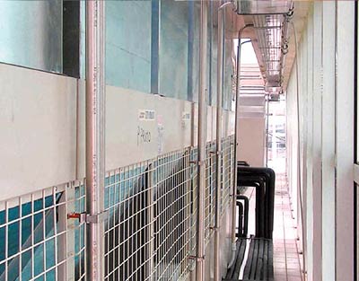
A view of the outdoor units of the VRF systems installed on the roof and concealed behind a wall element.
Here you can see the section of the machine exhaust duct to prevent the potential risk of short circuits between the air flows.
There is a circular calibration damper for each connection. This system allows the mixing of re-circulating air with clean, renewed air without disruption to the flow of air inside the rooms, which is always kept at an optimum speed of around 0.1m/sec.
Air recovered from rooms is partly exhausted and partly delivered to the indoor units via galvanised steel plate ducts.
Two centralised controllers have been installed: one for the systems on the third and fourth floor, and the other for the remainder of the building (ground, first and second floors). The main centralised control functions consist of setting the temperature and operating control parameters for each zone, running diagnosis tests on all the units, the de-activation of remote controls, sequential start-up procedures and the programming of operating modes for the various zones. It also has the facility of recording electricity consumption for utility.

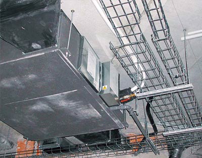
Detail of ducted indoor units above the ceiling during installation work.
Conclusions
This highly innovative achievement confirmed the importance of a meticulous study of the building-plant system ratio in order to achieve the results which are essential for advanced servicing of a modern building: full control over internal temperature and humidity conditions by users; low energy consumption (consequently resulting in minimal impact on the environment); a plant system capable of managing anticipated future changes to the distribution of internal space (a typical occurrence within office environments), with minimal intrusion of machinery and components. The positive relationship established with the architect who conceived the works was vital for selecting the system solutions which could optimally respond to all such requirements: the VRF primary air heat recovery systems. The solutions offered by Mitsubishi Electric, their technological content, wealth of management features and, most importantly, the availability of direct expansion handling units with primary air heat recovery units) have proved to be extremely efficient and fitting for the high standard of the works.
WORK PROJECT PARTICIPANTS
The project was carried out by Engineer Attilio Perlini, Studio Perlini S.r.l. Mantua.
Download
Ιστορικό της υπόθεσης
Download the complete Case History
Download

